You look at a VCR. You look at a grandfather clock. You look at the power meter on the side of your house with that little spinning wheel behind the plastic. Gears. Everywhere. They are in your transmission. They are in your differential. They are in that wind-up toy you forgot you owned. Any machine that spins parts needs them.
But most people just see teeth. They don’t see the math.
To understand what your car is actually doing when you shift, you need to get inside the head of the mechanism. It comes down to gear ratios and how those teeth talk to each other. Let’s strip it down.
Why Do We Even Use Gears?
It’s not just about making things spin. Gears do four specific jobs. That’s it.
- Reverse direction. Turn left, get right.
- Change speed. Go faster or slower.
- Move the axis. Spin here, drive there.
- Synchronize. Make sure part A and part B stay locked in step.
Simple. But the magic is in the ratio.
The Math Behind the Spin
Forget the complex formulas for a second. Think about circles.
Circumference equals diameter times pi. Roughly 3.14. If you have a gear with a 1-inch diameter, its outer edge is about 3.14 inches long.
Now imagine two gears. One is big. The other is exactly half the size.
When you roll the big gear once, it covers a certain distance. The small gear? It has to spin twice to cover that same ground.
That is a 2:1 gear ratio.
The small gear turns two times for every single turn of the big one. That’s the core concept. If you want to understand how a car accelerates or why low gear feels powerful, this is the foundation. The smaller gear spins more. The larger gear spins less. It’s that simple.
Why Teeth Matter (It’s Not Just for Show)
You could just use smooth wheels, right? No. Smooth wheels slip.
Gears have teeth for three reasons.
- No slippage. The teeth lock together. If the input shaft turns, the output shaft must turn. They are synchronized perfectly.
- Exact ratios. You don’t need a caliper to measure the diameter. You just count the teeth.
- Forgiveness. Manufacturing isn’t perfect. Diameters might be slightly off. But the tooth count is absolute.
Here is the rule that matters: Count the teeth.
If Gear A has 60 teeth and Gear B has 20 teeth, the ratio is 3:1. 60 divided by 20 is 3. The small gear turns three times for every one turn of the big one.
That’s how you calculate gear ratios without a degree in engineering. You count. You divide.
Chaining Them Up: Gear Trains
Sometimes you need more than 3:1. Maybe you need 100:1. You can’t make one gear that small and another that huge. It wouldn’t fit in a transmission case.
So you chain them together. This is called a gear train.
You connect multiple pairs of gears in sequence. The output of the first pair becomes the input for the next. Multiply the ratios. Stack the reduction.
This is how you get massive torque multiplication from a tiny input. It’s how your car climbs a hill in first gear. It’s not one big ratio. It’s a series of smaller ones working together.
Gears are just leverage. Rotational leverage.
Next, we look at how these trains are arranged in actual transmissions. Because putting them in a line is only one way to do it.
The Compound Gear Trick
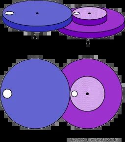
Look closer at that fuchsia gear on the right. It’s not a single solid piece. It’s a compound unit. Two gears, stacked vertically, rigidly connected. A smaller cog sits right on top of a larger one, rotating as if they were one.
This setup is standard for gear trains that need to change direction or ratio without adding extra shafts. You see it in everything from manual transmissions to clockwork. The point? Compactness and control.
Why Stack Gears Instead of Using Separate Shafts
You could run separate gears on separate axles, sure. But that eats up space. Stacking them means you get two different diameters, two different tooth counts, all sharing the same rotational axis.
The small gear drives one part of the system. The large gear drives another. Because they’re locked together, they spin at the same speed. But because their diameters differ, they interact with neighboring gears differently. One might speed things up. The other might torque down. It’s mechanical multitasking.
How This Affects the Rest of the Train
In the next figures, you’ll see this pattern repeat. Multiple gears in a sequence. Some single. Some compound like the fuchsia one. Each connection changes the output.
The magic isn’t in one big gear. It’s in how many small interactions chain together.
You don’t need exotic materials here. Just precise teeth, proper alignment, and that stacked design to keep the mechanism tight. Enthusiasts love it because it’s visible engineering. You can trace the power path with your eyes. No hidden actuators. Just metal pushing metal.
How a cascading gear train multiplies speed
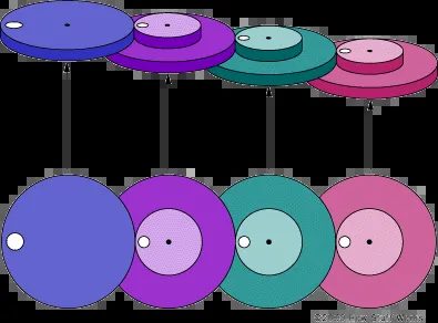
Look at that setup again. The fuchsia gear spins at double the speed of the purple one. Simple math. But the green gear? It turns at twice the rate of the fuchsia. Then the pink gear doubles the green’s output. You aren’t just adding speed. You’re stacking multipliers. Each stage compounds the rotation rate of the previous one.
This creates a much higher overall gear ratio than a single step-up could manage.
A multi-stage gear train allows for extreme speed multiplication in a compact space.
Why does this matter for cars? Because you rarely want one massive gear jump. It creates torque issues. It strains the drivetrain. Breaking it into stages—purple to fuchsia, fuchsia to green, green to pink—smooths out the mechanical demand. You get the final high-speed rotation without snapping your axles.
Think about it. If the purple gear turns once, the fuchsia turns twice. The green turns four times. The pink? Eight times. That’s an 8:1 ratio achieved through three small, manageable steps.
Is this common in modern transmissions? Not exactly like this, but the principle holds. Automatic transmissions use planetary gear sets that act similarly, stacking ratios to cover a wide range of speeds without needing physically impossible gear sizes.
The key takeaway is that compound gear trains let engineers achieve high final drive ratios or wide transmission spreads without making the entire gearbox the size of a refrigerator.
You get precision. You get range. And you keep the mechanical stress distributed.

How Gear Ratios Multiply Speed
Look at the size difference. The smaller gears here are exactly one-fifth the diameter of the big ones. That 1:5 ratio does heavy lifting. Hook a motor to the purple gear, spin it at 100 rpm, and the green gear next to it? It’s hitting 500 rpm. Keep going to the pink gear. Now you’re looking at 2,500 rpm.
It works both ways.
Attach a high-speed motor—2,500 rpm—to that pink gear, and the purple gear crawls along at a steady 100 rpm. You trade speed for torque. Or torque for speed. Depends on what you need.
This isn’t just theory. Open up an old-style electric meter. The kind with five mechanical dials instead of digital readouts. You’ll see this exact setup. Five dials linked by a gear train. Each step has a 10:1 ratio. One full turn of the fastest dial equals ten turns of the next one down.
Notice the numbers. They run backwards on adjacent dials. Since the gears mesh directly, they have to spin in opposite directions. One goes clockwise. The neighbor goes counter-clockwise. It’s mechanical logic. No exceptions.
Why Car Differentials Use Conical Gears
Gears do more than just change speed or direction in a straight line. You can bend the axis of rotation.
Enter conical gears. Also called bevel gears. These mesh at an angle, usually 90 degrees. The input spins one way. The output spins perpendicular to it.
Where do you see this? Almost every rear-wheel-drive car. Right in the differential.
The engine spins forward. The transmission sends power forward. But the wheels are on the sides. You need to turn that power 90 degrees to drive the axles. Conical gears make that turn. They take the longitudinal rotation from the driveshaft and redirect it into the transverse rotation of the rear wheels. Without them, your car would just drive backwards in a straight line. Or not at all.

Why planetary gear trains solve the ratio problem
Planetary gear trains exist to fix a specific headache. You want a 6:1 gear ratio. In a standard inline setup, you chain three gears together. The first drives the second. The second drives the third.
It works. It’s predictable. But it’s bulky. That third gear sticks out like a sore thumb. You lose space. You add weight. In a tight engine bay or a compact transmission case, that extra length is a dealbreaker.
Enter the planetary set. It packs that same 6:1 gear ratio into a single, compact unit. Instead of gears in a line, you stack them radially. A sun gear sits in the center. Planet gears orbit it. They’re held by a carrier. An outer ring gear encloses everything.
This isn’t just about saving room. It’s about torque capacity. Multiple planet gears share the load. The stress distributes across the teeth. You get higher power density. That’s why automatic transmissions and hybrid drivetrains rely on them. They handle the heat. They handle the torque. They don’t quit.
The planetary arrangement allows multiple gears to share the load, increasing durability without adding size.
So when you see a compact transmission with high reduction ratios, look for the planets. They’re doing the heavy lifting.
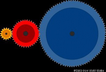
Planetary Gears For Coaxial Power In Electric Tools
The linear train described earlier works fine if you don’t mind the output shaft ending up somewhere else. The red gear is three times the diameter of the yellow one. The blue gear is twice the red. That gives you a 6:1 ratio. Simple. But what if you need the input and output on the same axis?
This is where things get interesting. You want the power to come in one end and leave the other, straight through. No offset. No extra space needed for a second shaft parallel to the first.
Look at an electric screwdriver. You hold it in one hand. The battery and motor are behind the chuck. The drill bit spins on the same centerline as the motor shaft. You can’t have a gear train sprawling out sideways. It wouldn’t fit. It wouldn’t work.
Enter the planetary gear system.
This setup solves the coaxial problem. It stacks the gears concentrically. The input spins the sun gear in the middle. Planet gears orbit around it. They mesh with a fixed ring gear on the outside. The carrier holds the planets and turns the output shaft.
This configuration allows high reduction ratios in a compact, coaxial package.
It’s efficient. It’s strong. It handles high torque loads without the shear stress that can plague simple spur gears under heavy load. The load is distributed across multiple planet gears. That means each gear carries less force. Less wear. Longer life.
You see this in EVs too. Tesla uses planetary gearsets in their powertrains. Single-speed transmissions don’t need complex shifting, but they need high torque multiplication at low speeds. Planetary gears deliver that without adding length to the drivetrain.
It’s not just about fitting in a tight space. It’s about structural integrity. The housing supports the gearset from all sides. The reaction forces cancel out internally. The bearing loads are lower compared to a parallel shaft setup where the gears push against each other sideways.
So why use a planetary system? Because you need coaxial alignment. Because you need compactness. Because you need to handle torque without breaking.
The math stays the same. The ratio depends on the tooth counts of the sun, planet, and ring gears. But the geometry changes everything. You trade simplicity for density. You trade visual clarity for mechanical efficiency.
Is it harder to manufacture? Yes. Precision matters more. The planets must be spaced perfectly. The carrier must be rigid. But for applications like screwdrivers, power windows, or EV drivetrains, it’s the only way to go.
You get your speed reduction. You get your torque multiplication. And you keep your input and output on the same line.
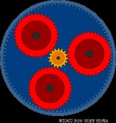
How planetary gears handle heavy loads
That yellow input gear hits all three red gears at once. They’re bolted to a single plate. Instead of biting into the outside of the blue ring, they mesh with the inside teeth.
Three red gears mean the load splits. The gear train gets tough. Really tough. The output shaft pulls power from that plate while the blue gear stays locked in place. It’s a classic planetary setup. You can actually see a two-stage version of this exact mechanism on the electric screwdriver page if you look closely.
Synchronizing distant gears with an idler
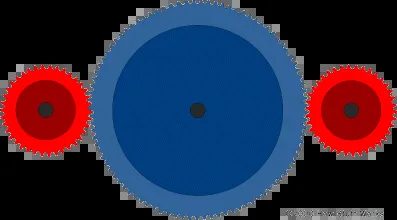
Here’s another practical scenario. You’ve got two red gears that need to spin in sync. But they’re far apart. How do you connect them without changing their rotation direction?
You drop a big gear between them. An idler gear.
It doesn’t change the speed ratio. It just flips the rotation twice. Once for the first mesh, again for the second. The net result? Both red gears turn the same way. It’s a simple fix for spacing issues.

Chain and Belt Drives: The Lightweight Alternative to Gears
So you want opposite rotation? Sure. Just slap two identical gears together. They’ll spin in reverse directions. Problem solved.
Except it’s not really solved. Not practically.
Those extra gears are heavy. You’re adding mass to a rotating assembly, which means more inertia, more stress on the bearings, and a whole lot of unnecessary complexity. You also need to machine axles for them. Precision bearings. Seals. It adds up fast, both in weight and cost.
The real-world fix? Ditch the direct mesh. Use a chain or a toothed belt.
It’s the standard solution for a reason.
Chains and belts transfer power between non-adjacent sprockets or pulleys, eliminating the need for intermediate idler gears and their associated hardware.
Look at the diagram. See how the drive crosses over? That’s the trick. By routing the drive medium in a figure-eight or crossed configuration, you flip the rotational direction without adding any extra rotating mass.
Why choose one over the other?
It comes down to tension, environment, and noise.
Chains are robust. They don’t slip. If you’re pushing serious torque or operating in a dirty, oily environment where rubber would degrade, a chain is your friend. But they’re noisy. They require lubrication. They wear over time, stretching the pitch, which means you eventually have to adjust the tension or replace the whole setup.
Toothed belts, like timing belts, are quieter. They’re lighter. They don’t need lube. But they can slip if overloaded or if the tension isn’t set correctly. They’re also sensitive to heat and chemicals.
For most automotive applications, especially where space is tight and weight matters, the belt wins on efficiency. The chain wins on durability in harsh conditions.
The crossed arrangement works for both. Just cross the belt or chain between the input and output pulleys/sprockets, and you get that reversed rotation you wanted, without the penalty of extra gears, axles, and bearings.
Simple. Effective. Lighter.
It’s why your engine’s camshaft might be driven by a belt that crosses over to reverse direction, or why some rear-wheel-drive conversions use a crossed chain drive to swap rotation without rebuilding the entire drivetrain layout.
You don’t always need more parts to change direction. Sometimes you just need to rearrange what you’ve got.

Why chains and belts win the distance game
Chains and belts have three big upsides. They’re light. They let you separate gears by a chunk of space. And they can link multiple gears at once.
Think about your engine’s timing setup. One toothed belt often drives the crankshaft, both camshafts, and even the alternator. Try doing that with solid gears. It gets messy fast. The geometry becomes a nightmare.
How to calculate gear ratio and why it matters
So how do you actually figure out a gear ratio?
Count the teeth.
Take the driver gear and the driven gear. Divide the number of teeth. If one gear has 60 teeth and the other has 20, you’ve got a 3:1 ratio. Simple math. No calculator needed unless you’re dealing with weird fractional counts.
Is a higher or lower gear ratio better?
It depends on what you care about.
Want better fuel mileage? Want less noise from the drivetrain? Go for a higher numerical gear ratio. Wait, that sounds counterintuitive. A higher number means the wheels turn fewer times per engine revolution. That keeps RPMs lower at highway speeds. Lower RPMs mean less strain and better MPG.
What about that 4.11 rear end ratio everyone talks about? It’s the sweet spot for everyday driving. Not too tall. Not too short. Just right for commuting.
Need to tow a trailer? You want torque. You want a higher ratio, like 4.56 or steeper. Anything lower than that will struggle under heavy loads. It’ll lug. It’ll overheat. Stick to the higher numbers if you’re hauling serious weight.
Which gear ratio is best for your car?
There is no single best gear ratio.
It all comes down to your tire size. Big tires change the effective final drive ratio. You have to compare the gear ratio against the overall tire diameter. A 4.10 ratio with 30-inch tires feels different than a 4.10 ratio with 35-inch tires.
Check a gear ratio calculator or a chart to see how tire size shifts your real-world performance. The numbers on paper don’t tell the whole story. The rubber on the road does.
Your effective gear ratio changes when you swap tire sizes. Always recalculate.